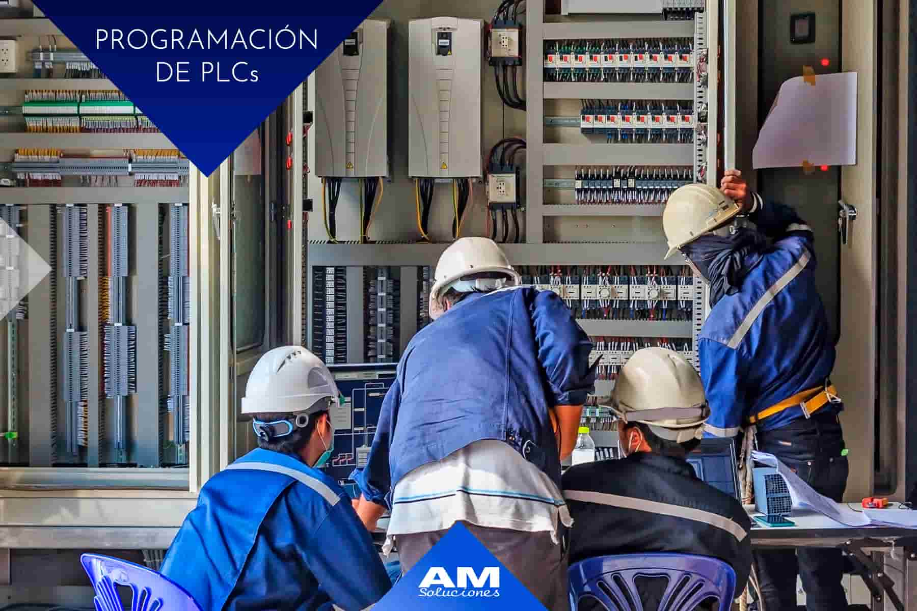
In this article we are going to explain and detail what PLC programming is and what it consists of. To do this, we will first define the concept of PLC programming. Next, we will talk about the phases that make up this type of programming and, finally, we will see what are the types of PLC programming that exist.
PLC acronyms refer to programmable logic controllers used in industrial automation processes.
These controllers were developed in the 1960s with the main function of controlling manufacturing activities that take place in industrial processes.
PLCs are made up of both hardware and software. They have an operating system (firmware) and a programming environment in which several languages can be used.
PLCs receive signals from various input channels that are connected to sensors installed in the machine in question or in the process that said machine controls. With this information, and through the implemented programming, it processes the information to make decisions and activate a series of outputs in the form of actuators, which can be electric, pneumatic, hydraulic, etc.
Through the programming of a PLC, a set of instructions and/or orders are generated that cause the execution or start-up of a specific task.
Industrial processes that are being carried out in real time can also be controlled and monitored at the same time.
The information they collect can be presented in a human-machine interface environment, or in higher control networks.
The areas in which a PLC system can be used are multiple: machine control, production chains, or process plant, among others.
At AM Soluciones we are experts in the implementation of this type of industrial communication to automate all types of processes efficiently, creating integrated processes and configuring network interfaces.
In this way, it is possible to automate production at all levels and use resources more efficiently.
PLC programming is made up of five phases that we will explain below:
1- Define and analyze the problem. The first thing to determine is what is the need or problem that you want to solve through a certain programmable control.
It will also be necessary to be clear about the results that you want to obtain from the system and the data that is necessary to be able to determine what the response of the machine will be.
2- Define the controller architecture. It will be necessary to determine what hardware the PLC will have and know what data or processes are going to be monitored in order to properly configure the controller inputs so that it can receive the data collected by the installed sensors.
3- Design of the algorithms. Algorithms are sequences that indicate the steps that are necessary to carry out each specific task. In this way, the indicated method will be designed and chosen to make the corresponding decisions.
4- Code programming. Once all the processes have been defined, the next step is to write the orders to establish communication with the machine. For this, it is essential to use the programming language that has previously been established.
5- Debugging, test and verification of the program. In this phase, those tasks are carried out that have the objective of verifying that the program works correctly.
An analysis is also carried out with which possible errors in communication can be detected. And finally, if necessary, the corresponding corrections are made in order to guarantee that the automation that has been programmed is running optimally.
1) Instruction List (IL or STL). This type of language is usually used for small applications, since its structure is very complex.
2) Structured Text (ST). It is a language that is used to encode complex arithmetic expressions that have both analog and digital values.
The difference with the list of instructions is that this language includes the formation of the tasks that the program will perform.
3) Ladder, Ladder or contact diagram (LD). This type of programming is the most widely used in the field of graphical interface.
It is a very advanced scheme that is used to record those logical structures of industrial controls.
Its name is due to the fact that this language imitates a ladder in two vertical rails and horizontal lines that represent the control circuits.
4) Block diagram (SFD). These block diagrams are used in engineering to explain in detail how they are or what are the flows that are established between a software system and a hardware system.
Through the representation that is made with these diagrams, schemes are obtained with which it is easier to understand the operations.
5) Sequential Function Chart (SFC). It is a representation made from sequential control diagrams in a program through which subroutines or stages are organized that indicate in chronological order what are the specific actions carried out by a program.
If you need more information about this type of industrial solutions, you can contact us through the form that is available on this website.
Our team of professionals in PLC programming will respond to you, in the shortest possible time, with a personalized proposal adapted to the specific needs of your business.